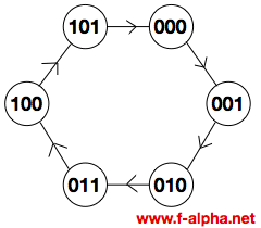
F-alpha.net: experiment 4 Mod 10 counter circuit diagram Design a mod-5 synchronous counter using d flip flop
mod 6 asynchronous 3bit counter - Multisim Live
[solved] please describe the logic circuit diagram of the modulo 6
Solved include the circuit diagram for your mod-16 counter
Mod 10 counter circuit diagramCounter mod diagram circuit flip mod6 flops experiment alpha reset electronics gate Mod 5 asynchronous counter circuit diagramMod counters are truncated modulus counters.
Mod 6 asynchronous 3bit counterMod counter using t flip-flop Mod 6 counter circuit diagramExcitation table of d flip flop.

J modulo 6
Design mod 6 asynchronous counter and explain glitch problem7490 decade counter pin configuration » hackatronic Mod 8 counter circuit diagram8-bit binary counter circuit diagram.
F-alpha.net: experiment 4Circuit diagram of mod 6 counter In the modulo 6 ripple counter shown in the figure. the output of the 2Mod 6 counter circuit diagram.

Counter modulo multisim asynchronous bit
Counter mod synchronousCopy of mod 8 synchronous counter using jk flip-flop Circuit diagram of mod 6 counter[diagram] 0 9 counter circuit diagram.
3-bit asynchronous up modulo 6 counterCounter asynchronous multisim Synchronous mod 6 counterMod 10 counter circuit diagram.
![[Solved] Please describe the logic circuit diagram of the modulo 6](https://i2.wp.com/www.coursehero.com/qa/attachment/22640454/)
Mod 10 counter circuit diagram
Circuit diagram of mod 6 counterMod 16 counter circuit diagram Asynchronous counter circuit diagramMod 6 counter circuit diagram.
[solved] draw the circuit diagram of a mod-32 synchronous counter usingCounter mod states experiment alpha mod6 reset illustration electronics Counters modulus truncated.